|
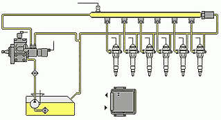
The common rail system essentially consists of three distinct (both functionally and as regards location) components. The high pressure pump prepares the pressure required for injection. Broadly speaking, it is designed as an axial or radial piston pump.
The rail is a hydraulic accumulator into which the high pressure pump delivers. Various forms are possible. Which one is used depends on the cylinder configuration of the engine. 
A cylindrical rail is mainly used for in-line engines. There is a pressure tapping point on the rail for the measuring of the system pressure. A regulating valve, which keeps the set system pressure constant by de-energizing a corresponding amount of fuel, is located on the pump or on the rail. The injection valves are termed injectors and are connected hydraulically to the rail.
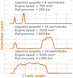
 In contrast to conventional valve body combinations, a magnetic valve is integrated. The high pressure pump is driven directly by the engine. In conjunction with the pressure regulation, it generates a constant system pressure (which can be set virtually at will across the whole engine speed range) which is present in the rail and consequently at every injector.
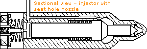
The system pressure is active in the injector, both in the nozzle chamber, which generates the opening force via pressure shoulders, as well in the control chamber, where it acts on the cross-sectional area of the control piston. The areas are selected such that the nozzle needle is closed by the system pressure. The magnetic valve is located above the control chamber. If it opens, the pressure in the control chamber falls. The difference in pressure between it and the nozzle chamber suffices to lift the nozzle needle. Fuel is injected.

Test
Tests are carried out at the IMKO (Institute for Machine Measurement and Piston Engines) using experiments and simulations. A test stand equipped with continuous quantity measuring, injection quantity indicator and various pressure and temperature measuring devices is available for the experimental tests. It is controlled by means of external control software (VS100). This allows free access to all applied parameters of the injection system. The software "Hydraulic network" made by Robert Bosch GmbH is used for the simulation. Two work stations are available for this purpose.
The focus is on investigating minimum quantity behaviour, sensitivity analysis and the influence of mechanical forces on the injector. The simulation results are adjusted according to measurements. The simulation model is modified and expanded in order to attain more precise results.
|


